Circuit Diagram Of The Serial Adder
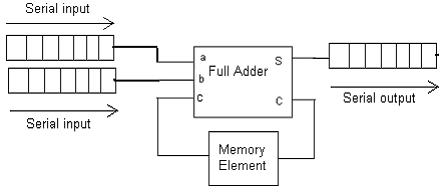
Adder serial bit subtractor parallel load number xilinx two negated schematics ise drawn Serial adder using mealy and moore fsm in vhdl – buzztech Figure 8.39 block diagram for the serial adder.
4-bit Serial Adder/Subtractor with Parallel Load – Altynbek Isabekov
Adder serial block diagram figure fsm state table transcribed text show Adder serial binary Vhdl code and circuit diagram for full adder
Serial adder
4-bit serial adder/subtractor with parallel load – altynbek isabekovAdder serial subtractor module schematics Adder circuit diagram vhdl codeSerial adder fsm moore circuit using table state type vhdl mealy fig assigned.
Adder serial flip flop circuit parallel binary bit logic flipflop use clock carry numbers sum two construct electronics add whichSerial adder bit diagram two 4-bit serial adder/subtractor with parallel load – altynbek isabekovAdder serial accumulator fsm signal.

Design of a serial binary adder
Solved design a control fsm for a 4-bit serial adder .
.


Figure 8.39 Block diagram for the serial adder. | Chegg.com

4-bit Serial Adder/Subtractor with Parallel Load – Altynbek Isabekov
VHDL Code and circuit Diagram For Full Adder - Engineering-Notes

4-bit Serial Adder/Subtractor with Parallel Load – Altynbek Isabekov

Design of a Serial Binary Adder

flipflop - Use of D flip-flop in Serial Adder - Electrical Engineering
SERIAL ADDER - ELECTRICAL ENCYCLOPEDIA